


Flexible Polyurethane Foam: Evaluation, Testing and Requirements
Flexible Polyurethane Foam Testing is an essential step in evaluating the quality, physical properties, and durability of flexible polyurethane foams. This article examines standardized methods for measuring density, indentation force deflection (IFD), compression force deflection (CFD), tensile strength, tear resistance, resilience, and foam fatigue. It also describes the classification and performance evaluation requirements for flexible foams under ISO 5999.
Abstract
Flexible polyurethane foams are used in a wide range of applications, including furniture, mattresses, automotive manufacturing, public transportation, medical equipment, and numerous industrial products, because of their comfort, flexibility, energy absorption, and adequate durability.
Given the diversity of these products, a standardized system for classification, quality evaluation, and definition of performance ranges is essential.
ISO 5999 and its corresponding Iranian national standard, INSO 8135:2026, provide a comprehensive framework for classifying flexible polyurethane foams.
Under this standard, foams are first divided by type and manufacturing process into three main types: slabstock foams (Type I), molded foams (Type II), and reconstituted or bonded foams (Type III). Each type is further subdivided according to resilience and foam structure into categories such as LB, MB, HB, LM, MM, HM, and RE, intended for specific applications.
Once the foam type has been established, its performance is evaluated by the constant-load pounding fatigue test according to ISO 3385. In this test, the foam specimen undergoes repeated loading cycles, and the reduction in hardness after testing is measured. The hardness-loss ratio indicates durability and the retention of mechanical properties during long-term use. Foams are consequently classified into five classes: X, V, S, A, and L. Lower hardness loss means greater fatigue resistance and suitability for more demanding service conditions.
Another key criterion in the standard is indentation force deflection (IFD), which indicates the force required to produce a specified indentation in the foam. This is the primary measure of initial foam hardness and is used to define grades. Complete foam identification therefore comprises type, class, and grade. For example, HB-V-170 (I) denotes high-resilience slabstock foam suitable for very severe applications, with an initial hardness of 170 N. This designation system makes selecting suitable foam for different applications easier and more precise.
In addition to defining the classification system, ISO 5999 specifies minimum physical-property requirements for each foam type and class, including tensile strength, elongation at break, compression set, strength after heat and humidity aging, percentage changes in strength, and other related properties. These requirements ensure that foam has sufficient durability under service conditions as well as appropriate hardness.
Finally, suitable foam cannot be selected on the basis of one parameter alone. Foam type, performance class, hardness grade, physical properties, actual service conditions, and application-specific requirements must be considered together. Compliance with international standards such as ISO 5999 supports product quality and durability, appropriate selection for different applications, and comparison of products from different manufacturers. Such standards therefore play an important role in the design, manufacture, quality control, and development of flexible polyurethane foams.
1- Introduction
During product development, the physical properties of foam are evaluated to identify raw-material characteristics and assess suitability for intended applications. In industrial foam production, measurement of key physical properties also plays an important role in product quality control.
This article introduces and explains tests for assessing basic physical properties and foam durability.

Figure 1 – Illustration of foam under load
2- Basic Physical Properties
ASTM D3574 provides standardized procedures for conditioning foam specimens and testing their basic physical properties and durability. There is no single direct ISO equivalent to this standard; however, some of the test methods it describes have corresponding or equivalent ISO standards. This article uses the relevant ISO standards in each section to explain the test methods. The following seven basic physical-property tests are considered:
Density
Indentation Force Deflection (IFD)
Compression Force Deflection (CFD)
Constant Deflection Compression Set
Tensile Strength
Tear Resistance
Resilience
2-1- Specimen Preparation
According to the ISO standards, foam testing should be carried out 72 hours after manufacture. Before testing, an undeformed foam specimen must be conditioned for at least 16 hours in a controlled environment at 23 ± 2°C and 50 ± 5% relative humidity (or at 27 ± 2°C and 65 ± 5% relative humidity). This conditioning period may include the final part of the period following manufacture.
For some tests, mechanical conditioning is also used to obtain results that more closely reflect the product’s actual performance in service.
2-2- Density
Density measurement, as illustrated in Figure 2, determines the apparent density or bulk density of the foam, rather than the true density of the polymer. This physical property is particularly important because it is directly related to manufacturing cost and load-bearing capacity. Generally, increasing density increases production cost but also improves the foam’s mechanical properties and load-bearing capacity.
According to ISO 845, foam density is determined and reported in two ways. The first is apparent core density, for which all skin layers formed during molding are removed before measuring the density of the foam core. The second is apparent overall density, measured with the skins retained and including all layers formed during molding. In this test, the dimensions of a representative foam specimen are measured accurately, followed by its mass. Density, usually reported in kilograms per cubic meter (kg/m³), is obtained by dividing specimen mass by volume.
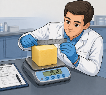
Figure 2 – Density measurement
2-3- Indentation Force Deflection (IFD)
The IFD test measures the load-bearing properties of foam. It measures the force needed to press a circular plate into the foam, a value also used as a foam hardness index. Experience has shown that the results can vary with the temperature and relative humidity of the environment in which the foam was manufactured, cured, and tested. Under ISO 2439, Method A, the specimen is placed on a perforated support plate that allows air to pass through. A circular plate 20 cm in diameter is then positioned on the foam surface (Figure 3). For preliminary mechanical conditioning, the specimen is compressed three times to 70% of its thickness. Immediately after the third unloading, indent the specimen by 40% of its thickness. Maintain this indentation for 30 seconds, record the corresponding force in newtons, and release the load. Applied force and indentation are recorded simultaneously.
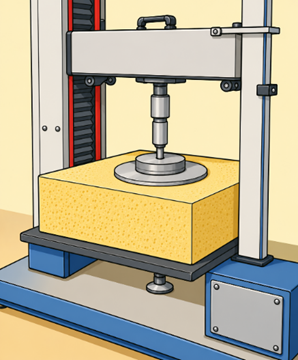
Figure 3 – Hardness measurement at constant strain
The results can be plotted as shown in Figure 4. At a given indentation, the force measured during unloading is lower than the force required during loading. This difference is called hysteresis and is expressed as a percentage of the applied force.
Hysteresis measures the energy absorbed by foam during deformation. Foams with high hysteresis exhibit lower resilience and generally require more time to return to their original shape.
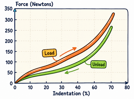
Figure 4 – Force–strain curve from the IFD test
IFD values may be measured and reported at several deformation levels, including 25%, 50%, and 65% of the foam’s initial thickness. Unloading IFD values are also commonly recorded at 25% and 5% deformation. These measurements provide various indices and technical information about the foam’s mechanical behavior and load-bearing properties, the most important of which are described below.
- Recovery, or the inverse of hysteresis (1/Hysteresis)
%Recovery=(Unload 25% IFD)/(Load 25% IFD)×100
High recovery values are desirable in comfort and cushioning applications, whereas low recovery values are better suited to shock absorption. Foams with low recovery are sometimes referred to as ‘dead foam’.
- Sag Factor, or Support Factor
Sag Factor=(65% IFD)/(25% IFD)
The higher the sag factor (support factor), the better the foam’s support and seating performance. Foams with a low sag factor generally bottom out quickly under load and perform poorly.
- Comfort Factor, or the inverse of the initial hardness factor
Comfort Factor=(25% IFD)/(5% IFD)
The comfort factor describes the initial sensation experienced by a user on contact with the foam surface. Higher values indicate a softer-feeling surface, while lower values indicate a firmer, harder surface.
- Guide Factor
25% Guide Factor=(25% IFD)/Density
65% Guide Factor=(65% IFD)/Density
Foams with a higher guide factor are generally more economical in terms of raw-material consumption and manufacturing cost; however, this advantage does not necessarily imply better performance.
2-4- Compression Force Deflection (CFD)
The CFD test follows measurement principles similar to those of the IFD test, but measures and reports the force needed to compress the foam to a specified deformation. In CFD testing, a compression platen large enough to apply force uniformly over the entire upper surface of the specimen is used.
Under ISO 3386, the specimen is placed on a perforated support plate to permit airflow during compression. Position the specimen at the center of the apparatus (Figure 5) and compress it using the platen at 100 mm/min until its thickness has been reduced to 70% of its initial value. Raise the platen at the same speed until the specimen returns to its initial thickness. Repeat this operation three times for mechanical conditioning. On the fourth compression, measure and record the pressure needed to reach the specified deformation, in kPa.
The CFD procedure may be varied, including changes to specimen dimensions (such as foam thickness) and compression-platen area. Such variations may affect the test results and measured values.
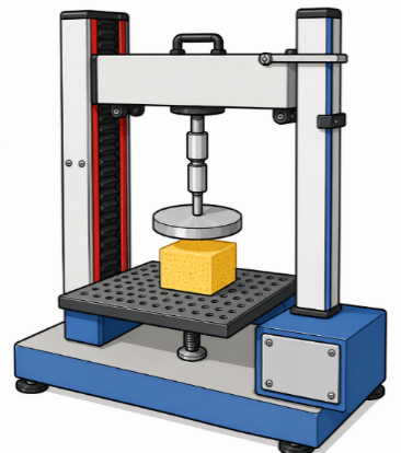
Figure 5 – Compression force measurement at constant strain
2-5- Constant Deflection Compression Set
In the compression set test, three precisely dimensioned foam specimens are placed between two metal plates and compressed to 50%, 75%, or 90% deformation relative to their original thickness. While held at that compression, they are kept at 70°C for 22 hours. The specimens are then removed and allowed 30 minutes to recover as far as possible toward their original shape. Finally, their thickness is measured again and the permanent deformation calculated.
C_t=(t_0-t_f)/t_0 ×100
C_t: compression set, expressed as a percentage of the specimen’s initial thickness;
t_0: initial specimen thickness before loading;
t_f: final specimen thickness after testing and recovery.
Provided that the specimen’s initial thickness is less than its length or width, compression set is independent of specimen thickness. If thickness exceeds length or width, however, the specimen may buckle during loading and the results may not be sufficiently repeatable. Specimens are therefore generally positioned so that compression set is measured in the foam-rise direction. Compression set values measured on specimens cut perpendicular to the foam-rise direction are generally lower.
In addition, some automotive manufacturers require wet compression set testing. In a common procedure, a cut specimen (with the molded skin retained, as in the method used by Renault) is tested at 50% compression for 22 hours at 50°C and 95% relative humidity.
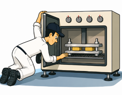
Figure 6 – Compression set test
2-6- Tensile Strength
The tensile test measures foam strength under tensile loading and provides information about its flexibility and elastic behavior. Specimens are generally cut into dumbbell or dog-bone shapes according to the dimensions specified in the applicable standard. During testing, the specimen is stretched at a constant rate (500 mm/min under ISO 1798) until rupture occurs. The force recorded at break is used to report the foam’s tensile strength, normally expressed in kilopascals (kPa).
The maximum extension of the specimen, expressed as a percentage of its original length, is called elongation at break. It is normally measured manually or with an extensometer. In the past, contact extensometers could introduce errors because contact with the specimen might deform it or create stress concentrations. Non-contact laser-based extensometers are now available for more precise measurement. The modulus of elasticity is obtained from the stress–strain curve recorded in the tensile test. It corresponds to the initial slope of that curve in the region where the material behaves elastically and Hooke’s law applies. Most polyurethane foams have a yield point, beyond which deformation is no longer fully recoverable and permanent, nonelastic deformation begins. This irreversible behavior may result from rupture of struts in the foam’s cellular structure, failure of cell windows, or slippage of polymer chains. The stress at the yield point is called yield strength.
For further information on how formulation ingredients affect foam structure and mechanical properties, see The Role of Chain Extenders in Polyurethane Foam.
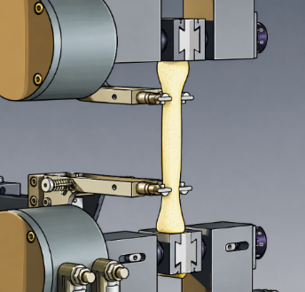
Figure 7 – Tensile strength measurement
2-7- Tear Resistance
Another important measure of foam mechanical strength is tear strength. As shown schematically in Figure 8, a specimen of dimensions specified by ISO 8067, with an initial slit, is subjected to a tensile force. As the force is applied, the tear propagates from the initial slit and the force needed to continue propagation is measured. Tear resistance is calculated by dividing the maximum or mean recorded force by specimen thickness and is normally reported in newtons per millimeter (N/mm). A higher tear-resistance value indicates greater resistance to crack or tear propagation under mechanical stress.
The test results depend substantially on the foam’s tear resistance, but do not necessarily correlate directly with tensile strength. In this test, tearing begins at a pre-existing slit; the main criterion is resistance to continued tear propagation rather than the force needed to initiate a tear. Accordingly, the quality and sharpness of the cutting tool can affect the measured results.
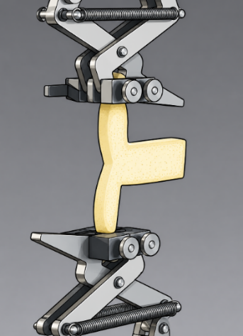
Figure 8 – Tear resistance measurement
2-8- Resilience
Foam resilience is measured using the ball rebound test, as illustrated below. A steel ball is dropped onto the foam specimen from a specified height, and its rebound height is measured. The procedure and required equipment are described in ISO 8307. The results show a useful correlation with the cushioning comfort of foam and are used as one indicator of this property.
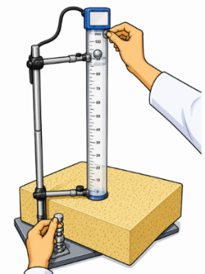
Figure 9 – Foam resilience test
3- Foam Durability Testing
Several laboratory methods are available for measuring fatigue resistance in flexible foams. Most fall into two main categories: static fatigue tests and dynamic fatigue tests.
Within these categories, methods differ in the magnitude of applied load or deformation, use of an indenter versus full compression, presence or absence of shear force, specimen thickness, number of loading cycles, loading and recovery rates, and rest periods between cycles or after testing. The measured indices also vary with the test and may include height loss, hardness loss, visual changes, or deterioration of other foam physical properties.
The following sections briefly describe several common standardized laboratory methods for evaluating foam fatigue. As research advances, new fatigue-test methods are being introduced at an increasing rate; many correlate more closely with real product performance and allow more accurate prediction of foam durability and performance.
3-1- Static Fatigue Tests
In general, two types of static fatigue test are most widely used:
- Constant Deflection Compression Set
- Constant-Load Creep Test
3-1-1- Constant Deflection Compression Set
The most common static fatigue test is the constant deflection compression set test, whose procedure is similar to the simple compression set test described in Section 2-5. It is performed according to ASTM D3574, Method I, generally using specimens measuring 380 × 380 × 80 mm. There is no equivalent ISO standard for this test. The foam specimen is compressed to a specified deformation in a simple apparatus, as shown in Figure 10, and held at that deformation for a set time. Afterward, the specimen is removed and allowed to recover. Its height is then measured and reported as a percentage of its initial height.
Compression set results correlate reasonably well with loss of cushion thickness under actual service conditions and with changes in foam hardness. However, a low compression set value in a static fatigue test does not necessarily guarantee satisfactory performance in use. For this reason, during new-product development, compression set tests are generally used only as approximate indicators of recovery after loading. They are also widely used for production quality control.
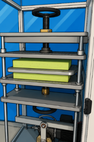
Figure 10 – Compression set test for static fatigue assessment
3-1-2- Constant-Load Creep Test
Creep is the time-dependent deformation of a specimen under a continuous constant load, which can recover fully or substantially after the load is removed. A typical test apparatus is shown in Figure 11. A foam specimen approximately 76 × 76 × 51 mm is placed beneath the loading platen. The platen is loaded to the required mass and positioned on the specimen. The specimen’s vertical deformation (creep) is measured over 10 minutes.
The test results are plotted as percentage deformation versus time, and the creep rate is calculated from the slope of the curve. Creep rate is related to the initial indentation or compression percentage: the greater the compression, the higher the creep rate. In general, a high creep rate indicates a greater tendency for foam to lose thickness and performance over time.
Like other static fatigue tests, the creep test alone is not severe enough to simulate actual service conditions. Its results are therefore generally insufficient to predict long-term performance accurately and are used primarily for comparative evaluation and quality control.
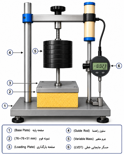
Figure 11 – Simplified illustration of a constant-load creep test apparatus
3-2- Dynamic Fatigue Tests
Dynamic fatigue tests are designed to simulate the repeated loads experienced by seat cushions in actual use. Two main types are generally employed:
Tests in which an oscillating indenter compresses the foam cushion to a constant percentage of its thickness.
Tests in which the specimen is repeatedly loaded and unloaded, with the indenter applying a constant load during each cycle.
Dynamic fatigue tests, including the constant-load pounder test—in which indenter penetration progressively increases as the foam softens—have been reported to correlate strongly with foam height loss and, to some extent, hardness loss under actual service conditions. One standardized method for constant-load pounding is ISO 3385, commonly used by many foam manufacturers in the furniture and automotive industries.
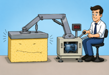
Figure 12 – Cartoon illustration of a foam fatigue test
3-2-1- Constant-Load Pounding Fatigue Test
ISO 3385 specifies the standard method for constant-load pounding fatigue testing. In this test, a foam specimen measuring 380 × 380 × 50 mm is repeatedly loaded with a circular platen 25 cm in diameter, under a load of 750 N at 70 cycles per minute, for a total of 80,000 cycles. An example of the pounding fatigue test apparatus is shown in Figure 13.
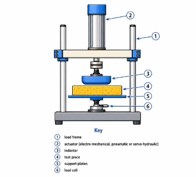
Figure 13 – Simplified illustration of a constant-load fatigue test apparatus
Specimen thickness and hardness (IFD values) are measured before and after testing according to ISO 2439. The measurements are compared, and their percentage losses are reported as indicators of foam fatigue performance and durability. However, when measuring IFD after the fatigue test, the 40% strain level is calculated on the basis of the originally measured thickness. This requirement is illustrated schematically in Figure 14.
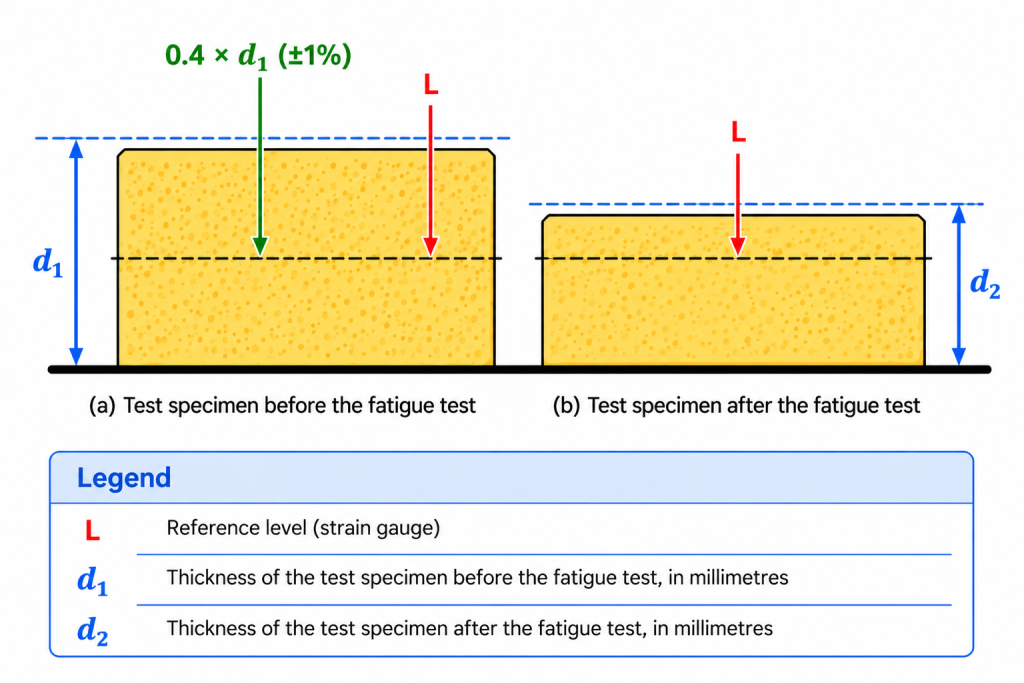
Figure 14 – Schematic of the hardness test procedure after foam fatigue
4- Physical-Property Requirements for Flexible Polyurethane Foams for Load-Bearing Applications
Foams are classified by foam type, fatigue-test performance, and indentation force deflection (IFD), which is used as the basis for grading. Based on this classification, ISO 5999 specifies requirements for the physical and mechanical properties of foams and recommends applications for each group according to its fatigue-test performance.
4-1- Classification of Flexible Polyurethane Foams
According to ISO 5999 (or the Iranian national standard INSO 8135:2026), foams are classified by type, class, and grade.
4-1-1- Type
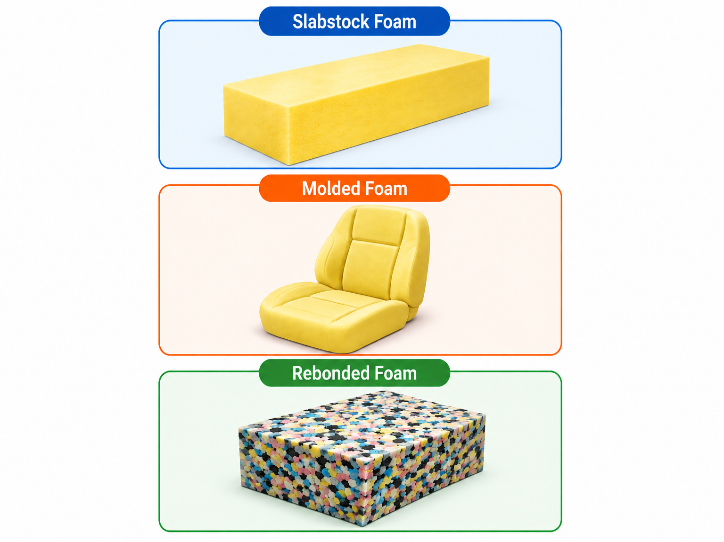
Figure 15 – Types of polyurethane foam
Flexible polyurethane foams are divided into groups according to raw-material type, foam structure, and production process. This classification under ISO 5999 forms the basis for determining the performance characteristics, physical requirements, and applications of each foam type. The types are presented in Table 1.
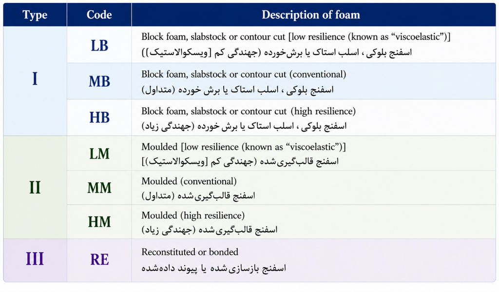
Table 1 – Foam types
Conventional foams and high-resilience (HR) foams behave differently in terms of physical properties. The two groups are mainly distinguished by resilience percentage and sag factor, two indicators that play important roles in comfort, body support, and overall foam performance. In general, HR foams have resilience greater than 60% and sag factors between 2.2 and 3.0, whereas conventional foams have resilience below 60% and sag factors between 1.7 and 2.0. The higher sag factor of HR foams indicates their greater ability to combine desirable initial softness with better body support at higher deformations, improving comfort and durability compared with conventional foams.
4-1-2- Grade

Figure 16 – Foam hardness (IFD) as an evaluation criterion
Polyurethane foam grades are determined by indentation force deflection (IFD), measured using Method A of ISO 2439, as shown in Table 2.
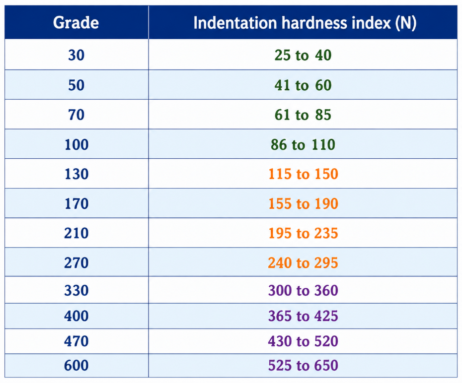
Table 2 – Foam grades based on initial hardness
4-1-3- Class
Except for MM and RE foams, the other foam types are classified into five classes according to their performance in the constant-load pounding fatigue test specified in ISO 3385. Each class represents the foam’s durability and retention of hardness after fatigue testing. The service conditions for each class and the permissible hardness-loss ratios are presented in Table 3.
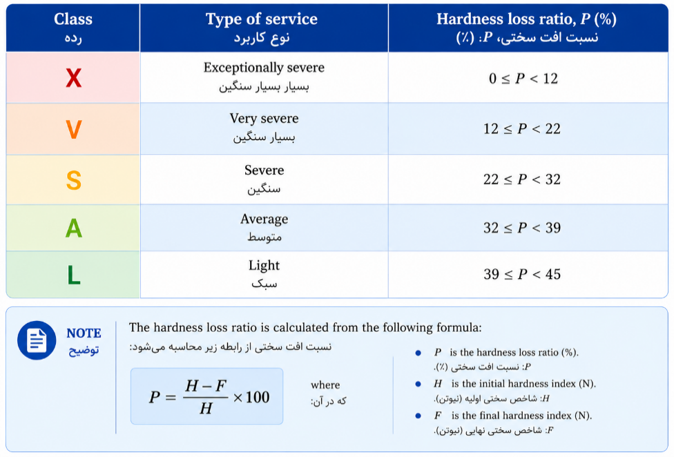
Table 3 – Foam classes and corresponding application types
In addition to Table 3, ISO 5999 provides graphs for determining foam class. Some are shown in Figure 17. Foam class can be determined graphically from the initial hardness index (Initial IFD) and hardness loss (H − F) after fatigue testing. Here, H denotes the initial hardness index and F the hardness index after fatigue testing.
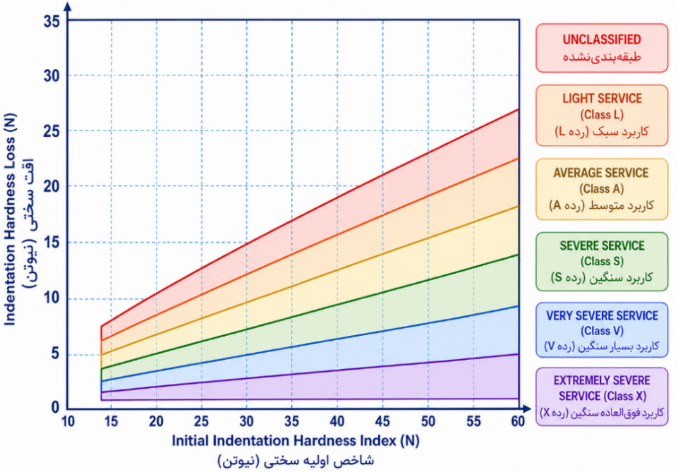
Figure 17 – Foam classification by initial hardness and hardness loss
4-2- Recommended Applications for Each Class of Flexible Polyurethane Foam
Because polyurethane foam classes are assigned on the basis of constant-load pounding fatigue test results, each class indicates resistance to different service conditions. In other words, foam showing less hardness loss after fatigue testing and placed in a higher class can be used in more demanding conditions and offer greater durability. However, class alone is insufficient for selecting suitable foam. Initial hardness (IFD) and foam thickness must also be considered, because actual performance depends on the combination of all three factors. For example, two foams may belong to the same class but behave differently in their final application because their initial hardness or thickness differs. Table 4 gives recommendations for typical applications of each foam class (from ISO 5999 or INSO 8135:2026). The class specified for each application is the minimum recommended class. Higher-class foams may also be used and will generally provide better durability and retention of properties throughout service.
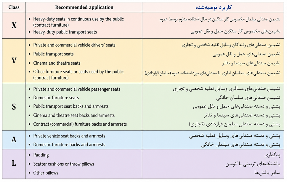
Table 4 – Recommended applications
4-3- Coding of Flexible Polyurethane Foams
Flexible polyurethane foams can be coded and classified according to type, class, and grade. Under this system, the foam type is given first, followed by its class and finally its grade. For example, HB-V-170(I) denotes high-resilience slabstock foam suitable for very severe service conditions, with an initial hardness index of 170 N.
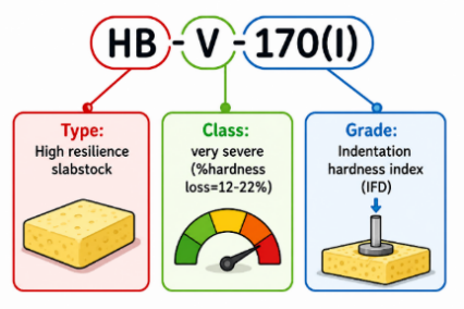
Figure 18 – Polyurethane foam coding
4-4- Physical-Property Requirements
Once foam type, class, and grade have been established, its physical properties must meet the requirements of the standard. Under ISO 5999 or the Iranian national standard INSO 8135:2026, an acceptable range of physical properties is defined for each foam type and class. The foam must satisfy these requirements, which provide a basis for assessing quality and ensuring appropriate performance in different applications. The permitted values for different foam types are presented in Table 5.
It should be noted that the requirements for classification, coding, and physical properties of combustion-modified flexible polyurethane foams are given in BS 3379.
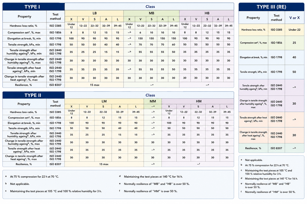
Table 5 – Physical-property requirements for flexible polyurethane foam types


